Pages

Powered By Blogger

Sunday, 27 May 2012

Machinist


www.kamps.com.my

Machinist at Work
A machinist is a person who uses machine tools to make or modify parts, primarily metal parts, a process known as machining. This is accomplished by using machine tools to cut away excess material much as a woodcarver cuts away excess wood to produce his work. In addition to metal, the parts may be made of many other kinds of materials, such as plastic or wood products. The goal of these cutting operations is to produce a part that conforms to a set of specifications, or tolerances, usually in the form of engineering drawings commonly known as blueprints.


Injection Mold


Related occupational titles.

Within the title machinist are other specialty titles that refer to specific skills that may be more highly developed to meet the needs of a particular job position. Some examples of these specialty titles are fitter, turning hand, mill hand, and grinder. Also, there are titles that are related but actually are a further development of machinist skills such as tool and die maker, tool maker, trim die maker, die sinker,patternmaker and mold maker. These latter titles are also more commonly found in specialized areas of industry.
A fitter and turner refers to a person who manufactures mechanical parts (turner) and assembles (fitter) those parts together to manufacture a mechanical device.

The role of the machinist in manufacturing
A machinist is usually called upon when a part needs to be produced from a material by cutting. Such a part may be unique or may be needed in the thousands. This could include a machinery part for a production line or anything that can be made from metal or plastic. Producing a part will often require several steps and more than one machine tool. Each machine tool plays a specific role in cutting away excess material. When large numbers of parts are needed, production planning is required to plan the most logical route using primarily computer numerically controlled (CNC) machines.
CNC Plasma Cutter
CNC machines are becoming the standard due to their speed, precision, flexibility, and reduced downtime while changing jobs. Production runs consisting of large numbers of parts are more cost effective (in a local and narrow sense) and commonly referred to as production work in the trade. Conversely, small production runs are sometimes referred to as prototype or jobbing work.
Production engineers use blueprints and engineering drawings to produce detailed specifications of the part, especially its geometry (shape), then decide on a strategy to make it. Machine tools are then configured by the machinist or toolsetter and production commences. The machinist works with the quality department to ensure the specifications are maintained in the finished product.

Materials commonly encountered by machinist.
Inconel Round Bar

A machinist is to metal as a woodcarver is to wood. The most common materials that machinists make parts from are steel, aluminum,brass, copper, and various alloys of these materials. Other less common materials such as vanadium, zinc, lead, or manganese are often used as alloying elements for the most common materials. Materials that machinists work with occasionally are plastics, rubber,glass, and wood products. Rarely, machinists also work with exotic and refractory metals. The term exotic metals is a general term describing out of the ordinary, rare or special purpose metals. A synonym might be space-age. A list of exotic metals might include, but is not limited to, titanium, beryllium, vanadium, chromium, molybdenum and tungsten, as well as special high-temperature metal alloys like Inconel or Hastelloy (sometimes called superalloys). Very often the meaning of the term suggests the need for specialized handling and/or tooling to machine them effectively.
Tungsten Carbide Cutter Tips
While the foregoing were primarily the materials that a machinist would be cutting, the cutters that the machinist uses must be harder and tougher than the materials to be cut. The materials in the cutters a machinist uses are most commonly high speed steel, tungsten carbide, ceramics, Borazon, and diamond.
Milling Process


Machinists usually work to very small tolerances, usually within 0.010" or 0.25 mm (more commonly expressed as ±0.010"(Plus or minus ten-thousands of an inch) or ±0.13 mm), and sometimes at tolerances as low as 0.0001" ((plus or minus one tenth of an thousand of an inch)0.0025 mm) for specialty operations. A machinist deals with all facets of shaping, cutting and some aspects of forming metal, except for welding, which is typically a separate trade. The operations most commonly performed by machinists are milling, drilling, turning, and grinding. There are other more specialized operations that a machinist will less frequently be called upon to perform such as honing, keyseating, lapping, and polishing, to name a few.
Tools of the machinist.
The tools that a machinist is expected to be proficient with fall into 6 broad categories:
Measuring Kit
  • Measuring tools: The measuring tools come several basic varieties:
  • Hand tools: The hand tools are the usual complement of tools found in a complete auto mechanic's set except that auto specialty tools would be absent and some outsized tools would likely be present, such as 1 1/2" (38 mm) open end wrench.
  • Machine tools: The machine tools have undergone a dramatic shift in the last 20 years. Manual machines have given way to computer numerically controlled machines (CNCs). For clarity's sake a categorization based on the historical groupings will be offered. Each of these groupings has been altered by the advent of CNCs and the CNCs meld some groups and blur the lines between others. In the past, the most common machine tools fall into 4 categories:
    Vertical Turret Lathe
    • Drilling machines, bench, floor, radial, and horizontal
    • Milling machines, horizontal, vertical, and boring mills
    • Turning machines, engine lathe, turret lathe, vertical turret lathe, vertical boring mill
    • Grinding machines, surface, cylindrical, centerless, universal
  • Workholders: The workholders may include vises, chucks, indexing accessories, pallets, specialty jigs or fixtures, and faceplates
  • Toolholders: The toolholders may include chucks, cutter adapters, cutter extension, tool posts, indexable turrets, box tools, quick change adapters, arbors, and collets.
  • Cutting tools: Cutting tools include various milling cutters such as face mills, shell mills, endmills, and form cutters; various drills,reamers, taps, countersinks, counterbores, and core drills; various turning tools, form tools, and threading tools; various grinding wheels distinguished by their geometry, bond, grit size, and compound.
Hand Tool Kit

Article from Wikipedia, the free encyclopedia


Contact us:

Website: www.kamps.com.my


Notice: Photos are used for illustrations purposes only and does not in any way express ownership or any title to the same.

Disclaimer

"All images are sourced from the internet and are in the public domain. We claim no credit for any images or videos featured on this site unless otherwise noted. All visual content is copyright to it's respectful owners. If you own rights to any of the images or videos, and do not wish them to appear on this site, please contact us via e-mail and they will be promptly removed. We are not responsible for content on any external website, and a link to such site does not signify endorsement. Information on this site may contain errors or inaccuracies; the site's proprietors do not make warranty as to the correctness or reliability of the site's content."


Saturday, 26 May 2012

Derrickman


www.kamps.com.my


Derrickman position varies greatly from one drilling rig to another. He almost always reports directly to the driller. The name derrickman comes from the position that he normally occupies, which is at the top of the derrick. From this position he guides the stands of drill pipe, typically 90 ft (27 meters) long, into the fingers at the top of the derrick while tripping (removing the drill string) out of the hole. When tripping into the hole (aka Running In) he will pull the pipe out of the fingers and guide it into the elevators suspended from the top drive. Traditionally the derrickman also works closely with the mud engineer (see drilling fluid) when not tripping pipe since he is not needed in the derrick. In this capacity it is his responsibility for monitoring the ph level, level of Calcium, viscosity and the mud weight (density), adding sacks of chemicals (25-100 lb each) to the mud or oil to maintain the desired properties, and monitor the mud level in the mud pits to aid in the well control. He is also responsible for the shale shakers and the mud pumps (making sure it runs good and fixing it when a fault occurs). The derrickman is also responsible for the transfer of additional fluids or chemicals (eg: Barite or Bentonite or oil-based fluids) from bulk silos or tanks (tank farm) to the mud system.


Article from Wikipedia, the free encyclopedia


Contact us:

Website: www.kamps.com.my


Notice: Photos are used for illustrations purposes only and does not in any way express ownership or any title to the same.

Disclaimer

"All images are sourced from the internet and are in the public domain. We claim no credit for any images or videos featured on this site unless otherwise noted. All visual content is copyright to it's respectful owners. If you own rights to any of the images or videos, and do not wish them to appear on this site, please contact us via e-mail and they will be promptly removed. We are not responsible for content on any external website, and a link to such site does not signify endorsement. Information on this site may contain errors or inaccuracies; the site's proprietors do not make warranty as to the correctness or reliability of the site's content."


Friday, 25 May 2012

Remotely Operated Vehicle (ROV)


www.kamps.com.my

ROV working on subsea structure

Remote control & monitors
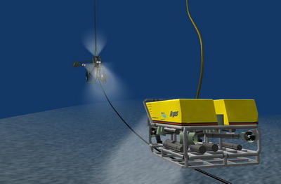
A remotely operated vehicle (ROV) is a tethered underwater vehicle. They are common in deepwater industries such as offshore hydrocarbon extraction. An ROV may sometimes be called a remotely operated underwater vehicle to distinguish it from remote control vehicles operating on land or in the air. ROVs are unoccupied, highly maneuverable and operated by a person aboard a vessel. They are linked to the ship by a tether (sometimes referred to as an umbilical cable), a group of cables that carry electrical power, video and data signals back and forth between the operator and the vehicle. High power applications will often use hydraulics in addition to electrical cabling. Most ROVs are equipped with at least a video camera and lights. Additional equipment is commonly added to expand the vehicle’s capabilities. These may include sonars, magnetometers, a still camera, a manipulator or cutting arm, water samplers, and instruments that measure water clarity, light penetration and temperature.
While the oil & gas industry uses the majority of ROVs; other applications include science, military and salvage. Science usage is discussed below, the military uses ROV for tasks such as mine clearing and inspection.


ROV at work
Construction

Conventional R.O.V.s are built with a large flotation pack on top of an aluminium chassis, to provide the necessary buoyancy. Syntactic foam is often used for the flotation. A tool sled may be fitted at the bottom of the system and can accommodate a variety of sensors. By placing the light components on the top and the heavy components on the bottom, the overall system has a large separation between the center of buoyancy and the center of gravity: this provides stability and the stiffness to do work underwater.
ROV Ship Hull Inspection
Electrical cables may be run inside oil-filled tubing to protect them from corrosion in seawater. Thrusters are usually in all three axes to provide full control. Cameras, lights and manipulators are on the front of the ROV or occasionally in the rear to help in maneuvering.
The majority of the work class ROVs are built as described above; however, this is not the only style in ROV building. Specifically, the smaller ROVs can have very different designs, each geared towards its own task.
Classification
Submersible ROVs are normally classified into categories based on their size, weight, ability or power. Some common ratings are:
Micro ROV
  • Micro - typically Micro class ROVs are very small in size and weight. Today’s Micro Class ROVs can weigh less than 3 kg. These ROVs are used as an alternative to a diver, specifically in places where a diver might not be able to physically enter such as a sewer, pipeline or small cavity.
  • Mini - typically Mini Class ROVs weigh in around 15 kg. Mini Class ROVs are also used as a diver alternative. One person may be able to transport the complete ROV system out with them on a small boat, deploy it and complete the job without outside help. Occasionally both Micro and Mini classes are referred to as "eyeball" class to differentiate them from ROVs that may be able to perform intervention tasks.
  • General - typically less than 5 HP (propulsion); occasionally small three finger manipulators grippers have been installed, such as on the very early RCV 225. These ROVUs may be able to carry a sonar unit and are usually used on light survey applications. Typically the maximum working depth is less than 1,000 metres though one has been developed to go as deep as 7,000 m.
  • Light Workclass - typically less than 50 hp (propulsion). These ROVs may be able to carry some manipulators. Their chassis may be made from polymers such as polyethylene rather than the conventional stainless steel or aluminium alloys. They typically have a maximum working depth less than 2000 m.
Heavy workclass ROV

  • Heavy Workclass - typically less than 220 hp (propulsion) with an ability to carry at least two manipulators. They have a working depth up to 3500 m.
  • Trenching/Burial - typically more than 200 hp (propulsion) and not usually greater than 500 hp (while some do exceed that) with an ability to carry a cable laying sled and work at depths up to 6000 m in some cases.
Cable burial/trenching
Submersible ROVs may be "free swimming" where they operate neutrally buoyant on a tether from the launch ship or platform, or they may be "garaged" where they operate from a submersible "garage" or "tophat" on a tether attached to the heavy garage that is lowered from the ship or platform. Both techniques have their pros and cons; however very deep work is normally done with a garage.
Submersible ROV

Article from Wikipedia, the free encyclopedia


Contact us:

Website: www.kamps.com.my


Notice: Photos are used for illustrations purposes only and does not in any way express ownership or any title to the same.

Disclaimer

"All images are sourced from the internet and are in the public domain. We claim no credit for any images or videos featured on this site unless otherwise noted. All visual content is copyright to it's respectful owners. If you own rights to any of the images or videos, and do not wish them to appear on this site, please contact us via e-mail and they will be promptly removed. We are not responsible for content on any external website, and a link to such site does not signify endorsement. Information on this site may contain errors or inaccuracies; the site's proprietors do not make warranty as to the correctness or reliability of the site's content."


Welding Inspector


www.kamps.com.my


Weld quality assurance is the use of technological methods and actions to test or assure the quality of welds, and secondarily to confirm the presence, location and coverage of welds. In manufacturing, welds are used to join two or more metal surfaces. Because these connections may encounter loads and fatigue during product lifetime, there is a chance they may fail if not created to proper specification.

Weld testing and analysis

Methods of weld testing and analysis are used to assure the quality and correctness of the weld after it is completed. This term generally refers to testing and analysis focused on the quality and strength of the weld, but may refer to technological actions to check for the presence, position and extent of welds. These are divided into destructive and non-destructive methods. A few examples of destructive testing include macro etch testing, fillet-weld break tests, transverse tension tests, and guided bend tests. Other destructive methods include acid etch testing, back bend testing, tensile strength break testing, nick break testing, and free bend testing. Non-destructive methods include fluorescent penetrate tests, magnaflux tests, eddy current (electromagnetic) tests, hydrostatic testing, tests using magnetic particles, X-rays and gamma ray based methods and acoustic emission techniques. Other methods include ferrite and hardness testing.

Imaging-based methods

X-ray-based weld inspection may be manual, performed by an inspector on X-ray-based images or video, or automated using machine vision.

Visible light imaging

Inspection may be manual, conducted by an inspector using imaging equipment, or automated usingmachine vision. Since the similarity of materials between weld and workpiece, and between good and defective areas, provides little inherent contrast, the latter usually requires methods other than simple imaging.
One (destructive) method involves the microscopic analysis of a cross section of the weld.
Ultrasonic Testing

Ultrasonic- and acoustic-based methods

Ultrasonic testing uses the principle that a gap in the weld changes the propagation of ultrasonic sound through the metal. One common method uses single-probe ultrasonic testing involving operator interpretation of an oscilloscope-type screen. Another senses using a 2D array of ultrasonic sensors. Conventional, phased array and time of flight diffraction (TOFD) methods can be combined into the same piece of test equipment.

Acoustic emission methods monitor for sound created by the loading or flexing of the weld.

Peel testing of spot welds

This method includes tearing the weld apart and measuring the size of the remaining weld.

Weld monitoring

Weld monitoring methods are used to assure the quality and correctness of the weld during the process of welding. The term is generally applied to automated monitoring for weld-quality purposes and secondarily for process-control purposes such as vision-based robot guidance. Visual weld monitoring is also performed during the welding process.
On vehicular applications, weld monitoring has the goal of enabling improvements in the quality, durability, and safety of vehicles – with cost savings in the avoidance of recalls to fix the large proportion of systemic quality problems that arise from suboptimal welding. Quality monitoring in general of automatic welding can save production downtime, and can reduce the need for product reworking and recall.
Industrial monitoring systems encourage high production rates and reduce scrap costs.

Transient thermal analysis method

Transient thermal analysis is used for range of weld optimization tasks.
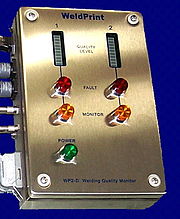
A WeldPrint Analyzer

Signature image processing method


Development
Signature image processing (SIP) is a technology for analyzing electrical data collected from welding processes. Acceptable welding requires exact conditions; variations in conditions can render a weld unacceptable. SIP allows the identification of welding faults in real time, measures the stability of welding processes, and enables the optimization of welding processes.
The idea of using electrical data analyzed by algorithms to assess the quality of the welds produced in robotic manufacturing emerged in 1995 from research by Associate Professor Stephen Simpson at the University of Sydney on the complex physical phenomena that occur in welding arcs. Simpson realized that a way of determining the quality of a weld could be developed without a definitive understanding of those phenomena. The development involved:
Arc Welding
  1. a method for handling sampled data blocks by treating them as phase-space portrait signatures with appropriate image processing. Typically, one second's worth of sampled welding voltage and current data are collected from GMAW pulse or short arc welding processes. The data is converted to a 2D histogram, and signal-processing operations such as image smoothing are performed.
  2. a technique for analyzing welding signatures based on statistical methods from the social sciences, such as principal component analysis. The relationship between the welding voltage and the current reflects the state of the welding process, and the signature image includes this information. Comparing signatures quantitatively using principal component analysis allows for the spread of signature images, enabling faults to be detected and identified The system includes algorithms and mathematics appropriate for real-time welding analysis on personal computers, and the multidimensional optimization of fault-detection performance using experimental welding data. Comparing signature images from moment to moment in a weld provides a useful estimate of how stable the welding process is. "Through-the-arc" sensing, by comparing signature images when the physical parameters of the process change, leads to quantitative estimates—for example, of the position of the weld bead.
Unlike systems that log information for later study or that use X-rays or ultrasound to check samples, SIP technology looks at the electrical signal and detects faults when they occur. Data blocks of 4,000 points of electrical data are collected four times a second and converted to signature images. After image processing operations, statistical analyses of the signatures provide quantitative assessment of the welding process, revealing its stability and reproducibility, and providing fault detection and process diagnostics. A similar approach, using voltage-current histograms and a simplified statistical measure of distance between signature images has been evaluated for tungsten inert gas (TIG) welding by researchers from Osaka University.

Industrial application

SIP provides the basis for the WeldPrint system, which consists of a front-end interface and software based on the SIP engine and relies on electrical signals alone. It is designed to be non-intrusive and sufficiently robust to withstand harsh industrial welding environments. The first major purchaser of the technology, GM Holden provided feedback that allowed the system to be refined in ways that increased its industrial and commercial value. Improvements in the algorithms, including multiple parameter optimization with a server network, have led to an order-of-magnitude improvement in fault-detection performance over the past five years.

The
 WeldPrint software received the Brother business software of the year award (2001); in 2003, the technology received the A$100,000 inaugural Australasian Peter Doherty Prize for Innovation; and WTi, the University of Sydney's original spin-off company, received an AusIndustry Certificate of Achievement in recognition of the development.WeldPrint for arc welding became available in mid-2001. About 70 units have been deployed since 2001, about 90% of them used on the shop floors of automotive manufacturing companies and of their suppliers. Industrial users include Lear (UK), Unidrive, GM Holden,Air International and QTB Automotive (Australia). Units have been leased to Australian companies such as Rheem, Dux, and OneSteelfor welding evaluation and process improvement.
SIP has opened opportunities for researchers to use it as a measurement tool both in welding and in related disciplines, such as structural engineering. Research opportunities have opened up in the application of biomonitoring of external EEGs, where SIP offers advantages in interpreting the complex signals

Article from Wikipedia, the free encyclopedia


Contact us:

Website: www.kamps.com.my


Notice: Photos are used for illustrations purposes only and does not in any way express ownership or any title to the same.

Disclaimer

"All images are sourced from the internet and are in the public domain. We claim no credit for any images or videos featured on this site unless otherwise noted. All visual content is copyright to it's respectful owners. If you own rights to any of the images or videos, and do not wish them to appear on this site, please contact us via e-mail and they will be promptly removed. We are not responsible for content on any external website, and a link to such site does not signify endorsement. Information on this site may contain errors or inaccuracies; the site's proprietors do not make warranty as to the correctness or reliability of the site's content."