Pages

Powered By Blogger

Friday, 25 May 2012

Welding Inspector


www.kamps.com.my


Weld quality assurance is the use of technological methods and actions to test or assure the quality of welds, and secondarily to confirm the presence, location and coverage of welds. In manufacturing, welds are used to join two or more metal surfaces. Because these connections may encounter loads and fatigue during product lifetime, there is a chance they may fail if not created to proper specification.

Weld testing and analysis

Methods of weld testing and analysis are used to assure the quality and correctness of the weld after it is completed. This term generally refers to testing and analysis focused on the quality and strength of the weld, but may refer to technological actions to check for the presence, position and extent of welds. These are divided into destructive and non-destructive methods. A few examples of destructive testing include macro etch testing, fillet-weld break tests, transverse tension tests, and guided bend tests. Other destructive methods include acid etch testing, back bend testing, tensile strength break testing, nick break testing, and free bend testing. Non-destructive methods include fluorescent penetrate tests, magnaflux tests, eddy current (electromagnetic) tests, hydrostatic testing, tests using magnetic particles, X-rays and gamma ray based methods and acoustic emission techniques. Other methods include ferrite and hardness testing.

Imaging-based methods

X-ray-based weld inspection may be manual, performed by an inspector on X-ray-based images or video, or automated using machine vision.

Visible light imaging

Inspection may be manual, conducted by an inspector using imaging equipment, or automated usingmachine vision. Since the similarity of materials between weld and workpiece, and between good and defective areas, provides little inherent contrast, the latter usually requires methods other than simple imaging.
One (destructive) method involves the microscopic analysis of a cross section of the weld.
Ultrasonic Testing

Ultrasonic- and acoustic-based methods

Ultrasonic testing uses the principle that a gap in the weld changes the propagation of ultrasonic sound through the metal. One common method uses single-probe ultrasonic testing involving operator interpretation of an oscilloscope-type screen. Another senses using a 2D array of ultrasonic sensors. Conventional, phased array and time of flight diffraction (TOFD) methods can be combined into the same piece of test equipment.

Acoustic emission methods monitor for sound created by the loading or flexing of the weld.

Peel testing of spot welds

This method includes tearing the weld apart and measuring the size of the remaining weld.

Weld monitoring

Weld monitoring methods are used to assure the quality and correctness of the weld during the process of welding. The term is generally applied to automated monitoring for weld-quality purposes and secondarily for process-control purposes such as vision-based robot guidance. Visual weld monitoring is also performed during the welding process.
On vehicular applications, weld monitoring has the goal of enabling improvements in the quality, durability, and safety of vehicles – with cost savings in the avoidance of recalls to fix the large proportion of systemic quality problems that arise from suboptimal welding. Quality monitoring in general of automatic welding can save production downtime, and can reduce the need for product reworking and recall.
Industrial monitoring systems encourage high production rates and reduce scrap costs.

Transient thermal analysis method

Transient thermal analysis is used for range of weld optimization tasks.
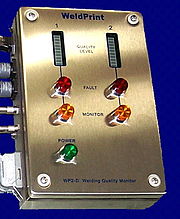
WeldPrint Analyzer

Signature image processing method


Development
Signature image processing (SIP) is a technology for analyzing electrical data collected from welding processes. Acceptable welding requires exact conditions; variations in conditions can render a weld unacceptable. SIP allows the identification of welding faults in real time, measures the stability of welding processes, and enables the optimization of welding processes.
The idea of using electrical data analyzed by algorithms to assess the quality of the welds produced in robotic manufacturing emerged in 1995 from research by Associate Professor Stephen Simpson at the University of Sydney on the complex physical phenomena that occur in welding arcs. Simpson realized that a way of determining the quality of a weld could be developed without a definitive understanding of those phenomena. The development involved:
Arc Welding
  1. a method for handling sampled data blocks by treating them as phase-space portrait signatures with appropriate image processing. Typically, one second's worth of sampled welding voltage and current data are collected from GMAW pulse or short arc welding processes. The data is converted to a 2D histogram, and signal-processing operations such as image smoothing are performed.
  2. a technique for analyzing welding signatures based on statistical methods from the social sciences, such as principal component analysis. The relationship between the welding voltage and the current reflects the state of the welding process, and the signature image includes this information. Comparing signatures quantitatively using principal component analysis allows for the spread of signature images, enabling faults to be detected and identified The system includes algorithms and mathematics appropriate for real-time welding analysis on personal computers, and the multidimensional optimization of fault-detection performance using experimental welding data. Comparing signature images from moment to moment in a weld provides a useful estimate of how stable the welding process is. "Through-the-arc" sensing, by comparing signature images when the physical parameters of the process change, leads to quantitative estimates—for example, of the position of the weld bead.
Unlike systems that log information for later study or that use X-rays or ultrasound to check samples, SIP technology looks at the electrical signal and detects faults when they occur. Data blocks of 4,000 points of electrical data are collected four times a second and converted to signature images. After image processing operations, statistical analyses of the signatures provide quantitative assessment of the welding process, revealing its stability and reproducibility, and providing fault detection and process diagnostics. A similar approach, using voltage-current histograms and a simplified statistical measure of distance between signature images has been evaluated for tungsten inert gas (TIG) welding by researchers from Osaka University.

Industrial application

SIP provides the basis for the WeldPrint system, which consists of a front-end interface and software based on the SIP engine and relies on electrical signals alone. It is designed to be non-intrusive and sufficiently robust to withstand harsh industrial welding environments. The first major purchaser of the technology, GM Holden provided feedback that allowed the system to be refined in ways that increased its industrial and commercial value. Improvements in the algorithms, including multiple parameter optimization with a server network, have led to an order-of-magnitude improvement in fault-detection performance over the past five years.

The
 WeldPrint software received the Brother business software of the year award (2001); in 2003, the technology received the A$100,000 inaugural Australasian Peter Doherty Prize for Innovation; and WTi, the University of Sydney's original spin-off company, received an AusIndustry Certificate of Achievement in recognition of the development.WeldPrint for arc welding became available in mid-2001. About 70 units have been deployed since 2001, about 90% of them used on the shop floors of automotive manufacturing companies and of their suppliers. Industrial users include Lear (UK), Unidrive, GM Holden,Air International and QTB Automotive (Australia). Units have been leased to Australian companies such as Rheem, Dux, and OneSteelfor welding evaluation and process improvement.
SIP has opened opportunities for researchers to use it as a measurement tool both in welding and in related disciplines, such as structural engineering. Research opportunities have opened up in the application of biomonitoring of external EEGs, where SIP offers advantages in interpreting the complex signals

Article from Wikipedia, the free encyclopedia


Contact us:

Website: www.kamps.com.my


Notice: Photos are used for illustrations purposes only and does not in any way express ownership or any title to the same.

Disclaimer

"All images are sourced from the internet and are in the public domain. We claim no credit for any images or videos featured on this site unless otherwise noted. All visual content is copyright to it's respectful owners. If you own rights to any of the images or videos, and do not wish them to appear on this site, please contact us via e-mail and they will be promptly removed. We are not responsible for content on any external website, and a link to such site does not signify endorsement. Information on this site may contain errors or inaccuracies; the site's proprietors do not make warranty as to the correctness or reliability of the site's content."


Tuesday, 8 May 2012

Pipelaying Ship


www.kamps.com.my


pipelaying ship is a maritime vessel used in the construction of subsea infrastructure. It serves to connect oil production platforms with refineries on shore. To accomplish this goal a typical pipelaying vessel carries a heavy lift crane, used to install pumps and valves, and equipment to lay pipe between subsea structures.
Lay methods consist of S-lay and J-lay and can be reel-lay or welded length by length. Pipe-laying ships make use of dynamic positioning systems or anchor spreads to maintain the correct position and speed while laying pipe.
Recent advances have been made, with pipe being laid in water depths of more than 2,500 metres.
The term "pipelaying vessel" or "pipelayer" refers to all vessels capable of laying pipe on the ocean floor. It can also refer to "dual activity" ships. These vessels are capable of laying pipe on the ocean floor in addition to their primary job. Examples of dual activity pipelayers include barges, modified bulk carriers, modified drillships semi-immersible laying vessels among others


Article from Wikipedia, the free encyclopedia


Contact us:

Website: www.kamps.com.my


Notice: Photos are used for illustrations purposes only and does not in any way express ownership or any title to the same.

Disclaimer

"All images are sourced from the internet and are in the public domain. We claim no credit for any images or videos featured on this site unless otherwise noted. All visual content is copyright to it's respectful owners. If you own rights to any of the images or videos, and do not wish them to appear on this site, please contact us via e-mail and they will be promptly removed. We are not responsible for content on any external website, and a link to such site does not signify endorsement. Information on this site may contain errors or inaccuracies; the site's proprietors do not make warranty as to the correctness or reliability of the site's content."


Kamps Energy (M) Sdn Bhd: Oil Platform

Kamps Energy (M) Sdn Bhd: Oil Platform: Follow @kampsenergy www.kamps.com.my An  oil platform , also referred to as an  offshore platform  or, somewhat incorrectly,  oil r...

Oil Platform


www.kamps.com.my


An oil platform, also referred to as an offshore platform or, somewhat incorrectly, oil rig, is a large structure with facilities to drill wells, to extract and process oil and natural gas, and to temporarily store product until it can be brought to shore for refining and marketing. In many cases, the platform contains facilities to house the workforce as well.
Depending on the circumstances, the platform may be fixed to the ocean floor, may consist of an artificial island, or may float.
Remote subsea wells may also be connected to a platform by flow lines and by umbilical connections; these subsea solutions may consist of one or more subsea wells, or of one or more manifold centres for multiple wells.
Types
Larger lake- and sea-based offshore platforms and drilling rigs are some of the largest moveable man-made structures in the world. There are several types of oil platforms and rigs:

Fixed platforms

  A fixed platform base 
These platforms are built on concrete or steel legs, or both, anchored directly onto the seabed, supporting a deck with space for drilling rigs, production facilities and crew quarters. Such platforms are, by virtue of their immobility, designed for very long term use (for instance the Hibernia platform). Various types of structure are used, steel jacket, concrete caisson, floating steel and even floating concrete. Steel jackets are vertical sections made of tubular steel members, and are usually piled into the seabed. Concrete caisson structures, pioneered by the Condeep concept, often have in-built oil storage in tanks below the sea surface and these tanks were often used as a flotation capability, allowing them to be built close to shore (Norwegian fjords and Scottish firths are popular because they are sheltered and deep enough) and then floated to their final position where they are sunk to the seabed. Fixed platforms are economically feasible for installation in water depths up to about 1,700 ft (520 m).

[edit]Compliant towers

These platforms consist of slender flexible towers and a pile foundation supporting a conventional deck for drilling and production operations. Compliant towers are designed to sustain significant lateral deflections and forces, and are typically used in water depths ranging from 1,200 to 3,000 feet (370 to 910 m).

[edit]Semi-submersible platform

These platforms have hulls (columns and pontoons) of sufficient buoyancy to cause the structure to float, but of weight sufficient to keep the structure upright. Semi-submersible platforms can be moved from place to place; can be ballasted up or down by altering the amount of flooding in buoyancy tanks; they are generally anchored by combinations of chain, wire rope or polyester rope, or both, during drilling or production operations, or both, though they can also be kept in place by the use of dynamic positioning. Semi-submersibles can be used in water depths from 200 to 10,000 feet (60 to 3,000 m).

[edit]Jack-up drilling rigs

 jackup rig
Jack-up Mobile Drilling Units (or jack-ups), as the name suggests, are rigs that can be jacked up above the sea using legs that can be lowered, much like jacks. These MODUs (Mobile Offshore Drilling Units) are typically used in water depths up to 400 feet (120 m), although some designs can go to 550 ft (170 m) depth. They are designed to move from place to place, and then anchor themselves by deploying the legs to the ocean bottom using a rack and pinion gear system on each leg.

[edit]Drillships

A drillship is a maritime vessel that has been fitted with drilling apparatus. It is most often used for exploratory drilling of new oil or gas wells in deep water but can also be used for scientific drilling. Early versions were built on a modified tanker hull, but purpose-built designs are used today. Most drillships are outfitted with a dynamic positioning system to maintain position over the well. They can drill in water depths up to 12,000 ft (3,700 m).[5]

[edit]Floating production systems

The main types of floating production systems are FPSO (floating production, storage, and offloading system). FPSOs consist of large monohull structures, generally (but not always) shipshaped, equipped with processing facilities. These platforms are moored to a location for extended periods, and do not actually drill for oil or gas. Some variants of these applications, called FSO (floating storage and offloading system) or FSU (floating storage unit), are used exclusively for storage purposes, and host very little process equipment. This is one of the best sources for having floating production.

[edit]Tension-leg platform

TLPs are floating platforms tethered to the seabed in a manner that eliminates most vertical movement of the structure. TLPs are used in water depths up to about 6,000 feet (2,000 m). The "conventional" TLP is a 4-column design which looks similar to a semisubmersible. Proprietary versions include the Seastar and MOSES mini TLPs; they are relatively low cost, used in water depths between 600 and 4,300 feet (180 and 1,300 m). Mini TLPs can also be used as utility, satellite or early production platforms for larger deepwater discoveries.


[edit]Gravity-based structure

A GBS can either be steel or concrete and is usually anchored directly onto the seabed. Steel GBS are predominantly used when there is no or limited availability of crane barges to install a conventional fixed offshore platform, for example in the Caspian Sea. There are several steel GBS in the world today (e.g. offshore Turkmenistan Waters (Caspian Sea) and offshore New Zealand). Steel GBS do not usually provide hydrocarbon storage capability. It is mainly installed by pulling it off the yard, by either wet-tow or/and dry-tow, and self-installing by controlled ballasting of the compartments with sea water. To position the GBS during installation, the GBS may be connected to either a transportation barge or any other barge (provided it is large enough to support the GBS) using strand jacks. The jacks shall be released gradually whilst the GBS is ballasted to ensure that the GBS does not sway too much from target location.

[edit]Spar platforms

 Spar Platform
Spars are moored to the seabed like TLPs, but whereas a TLP has vertical tension tethers, a spar has more conventional mooring lines. Spars have to-date been designed in three configurations: the "conventional" one-piece cylindrical hull, the "truss spar" where the midsection is composed of truss elements connecting the upper buoyant hull (called a hard tank) with the bottom soft tank containing permanent ballast, and the "cell spar" which is built from multiple vertical cylinders. The spar has more inherent stability than a TLP since it has a large counterweight at the bottom and does not depend on the mooring to hold it upright. It also has the ability, by adjusting the mooring line tensions (using chain-jacks attached to the mooring lines), to move horizontally and to position itself over wells at some distance from the main platform location. The first production spar was Kerr-McGee'sNeptune, anchored in 1,930 ft (590 m) in the Gulf of Mexico; however, spars (such as Brent Spar) were previously used as FSOs.
Eni's Devil's Tower located in 5,610 ft (1,710 m) of water, in the Gulf of Mexico, was the world's deepest spar until 2010. The world's deepest platform is currently the Perdido spar in the Gulf of Mexico, floating in 2,438 meters of water. It is operated by Royal Dutch Shell and was built at a cost of $3 billion.
The first truss spars were Kerr-McGee's Boomvang and Nansen. The first (and only) cell spar is Kerr-McGee's Red Hawk.

[edit]Normally unmanned installations (NUI)

These installations (sometimes called toadstools) are small platforms, consisting of little more than a well bayhelipad and emergency shelter. They are designed to be operated remotely under normal conditions, only to be visited occasionally for routine maintenance orwell work.

[edit]Conductor support systems

These installations, also known as satellite platforms, are small unmanned platforms consisting of little more than a well bay and a small process plant. They are designed to operate in conjunction with a static production platform which is connected to the platform by flow lines or by umbilical cable, or both.


Article from Wikipedia, the free encyclopedia


Contact us:

Website: www.kamps.com.my


Notice: Photos are used for illustrations purposes only and does not in any way express ownership or any title to the same.

Disclaimer

"All images are sourced from the internet and are in the public domain. We claim no credit for any images or videos featured on this site unless otherwise noted. All visual content is copyright to it's respectful owners. If you own rights to any of the images or videos, and do not wish them to appear on this site, please contact us via e-mail and they will be promptly removed. We are not responsible for content on any external website, and a link to such site does not signify endorsement. Information on this site may contain errors or inaccuracies; the site's proprietors do not make warranty as to the correctness or reliability of the site's content."